Victron VE.Bus BMS
Victron VE.Bus BMS
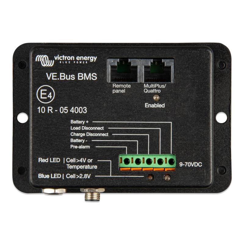
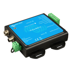
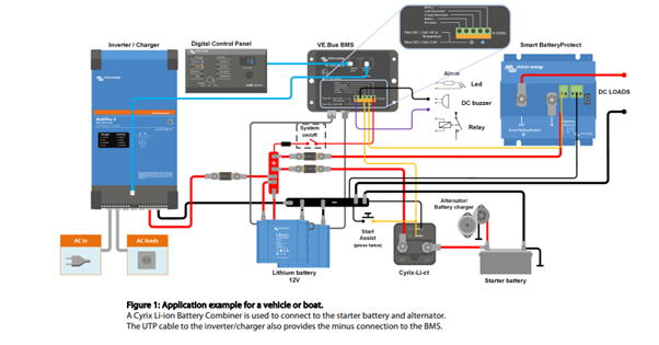
The VE.Bus BMS is a Battery Management System (BMS) designed to interface with and protect a single, or multiple Victron Lithium Battery Smart 12,8V & 25,6V (LiFePO4 or LFP) in systems that have Victron inverters or inverter/chargers with VE.Bus communication. It monitors and protects the batteries against over voltage and under voltage of any individual cell, and also over temperature or under temperature conditions.
Based on the status of the battery or batteries, the BMS will:
- Generate a pre-alarm signal to alert of an imminent cell under voltage condition.
- Disable inverting in VE.Bus inverters or inverter/chargers via VE.Bus, and disable other loads via the 'Load Disconnect' terminal in the event of a cell under voltage condition.
- Disable charging in VE.Bus inverters or inverter/chargers via VE.Bus and disable other chargers via the 'Charge Disconnect' terminal in the event of a cell overvoltage, under temperature or over temperature condition.
- Remote on/off terminals.
- Ability to disable VE.Direct and VE.Can solar chargers via a GX device.
- Allowing control of the VE.Bus inverter/charger from multiple devices, like the Digital Multi Control, the VE.Bus Smart dongle and/or a GX device.
- Auxiliary power input and output terminals that allow a GX device to remain powered in the event of a system shutdown.
Victron VE.Bus BMS
Protects each individual cell of a Victron lithium iron phosphate (LiFePO4 or LFP) battery
Each individual cell of a LiFePO4 battery must be protected against over voltage, under voltage and over temperature. Victron LiFePO4 batteries have integrated Balancing, Temperature and Voltage control (acronym: BTV) and connect to the VE.Bus BMS with two M8 circular connector cord sets. The BTVs of several batteries can be daisy chained. Up to five batteries can be paralleled and up to four batteries can be series connected (BTVs are simply daisy-chained) so that a 48V battery bank of up to 1500Ah can be assembled. Please see our LiFePO4 battery documentation for details.
The BMS will:
- shut down or disconnect loads in case of imminent cell under voltage,
- reduce charge current in case of imminent cell overvoltage or over temperature (VE.Bus products only, see below), and
- shut down or disconnect battery chargers in case of imminent cell overvoltage or over temperature.
Protects 12V, 24V and 48V systems
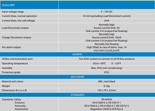
The operating voltage range of the BMS: 9 to 70V DC
Communicates with all VE.Bus products
The VE.Bus BMS connects to a MultiPlus, Quattro or Phoenix inverter with a standard RJ45 UTP cable.
Load Disconnect
The Load Disconnect output is normally high and becomes free floating in case of imminent cell under voltage (default 3,1V/cell, adjustable on the battery between 2,85V and 3,15V per cell). Maximum current: 2A.
The Load Disconnect output can be used to control.
- the remote on/off of a load, and/or
- the remote on/off of an electronic load switch (Battery Protect)
Pre-alarm
The pre-alarm output is normally free floating and becomes high in case of imminent cell under voltage (default 3,1V/cell, adjustable on the battery between 2,85V and 3,15V per cell). Maximum current: 1A (not short circuit protected). The minimum delay between pre-alarm and load disconnect is 30 seconds.
Charge Disconnect
The Charge Disconnect output is normally high and becomes free floating in case of imminent cell over voltage or over temperature. Maximum current: 10mA.
The Charge Disconnect output can be used to control
- the remote on/off of a charger and/or
- a Cyrix-Li-Charge relay and/or
- a Cyrix-Li-ct Battery Combiner
LED indicators
- Enabled (blue): VE.Bus products are enabled.
- Cell>4V or temperature (red): charge disconnect output low because of imminent cell over voltage or over temperature.
- Cell>2,8V (blue): load disconnect output high.
Reviews
No customer reviews for the moment.
You need to be logged in or create an account to give your appreciation of a review.


