


There are no more items in your cart


The VE.Bus BMS V2 is a Battery Management System (BMS) designed to interface with and protect a single, or multiple Victron Lithium Battery Smart 12,8V & 25,6V (LiFePO4 or LFP) in systems that have Victron inverters or inverter/chargers with VE.Bus communication. It monitors and protects the batteries against over voltage and under voltage of any individual cell, and also over temperature or under temperature conditions.
Based on the status of the battery or batteries, the BMS will:
The VE.Bus BMS V2 is the next generation of the VE.Bus Battery Management System (BMS) for Victron Energy Lithium Battery Smart batteries. These batteries are Lithium Iron Phosphate (LiFePO4) batteries and are available in 12.8 V or 25.6 V in various capacities. They can be connected in series, parallel and series/parallel so that a battery bank can be built for system voltages of 12 V, 24 V or 48 V. The maximum number of batteries in one system is 20, which results in a maximum energy storage of 84 kWh in a 12 V system and up to 102 kWh in a 24 V1) and 48 V1) system. It is designed to interface with and protect the lithium batteries in systems that have Victron inverters or inverter/chargers that have VE.Bus communication.
For reliable and safe operation, a LiFePO₄ battery must be monitored and protected against over voltage and under voltage of any individual cell, and also over temperature or under temperature conditions. The Victron Lithium Battery Smart range includes integrated cell voltage monitoring, cell voltage balancing, and temperature monitoring. If the cell voltage or battery temperature is outside of the allowable range, this is communicated to the BMS via two BMS cables with M8 circular connectors. In systems with multiple batteries, the BMS cables of each battery are connected in series (daisy chained), with the first and the last BMS cables connected to the BMS.
Based on the status of the Victron Lithium Battery Smart or batteries, the BMS will:
• Generate a pre-alarm signal to alert of an imminent cell under voltage condition.
• Disable inverting in VE.Bus inverters or inverter/chargers via VE.Bus, and disable other loads via the “Load Disconnect” terminal in the event of a cell under voltage condition.
• Disable charging in VE.Bus inverters or inverter/chargers via VE.Bus, disable VE.Direct and VE.Can solar chargers via a GX device and disable other chargers via the 'Charge Disconnect' terminal in the event of a cell overvoltage, under temperature or over temperature condition.
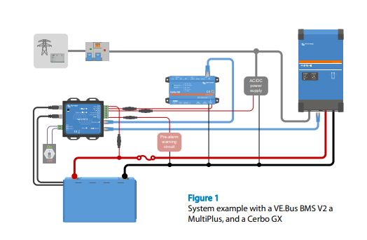
MultiPlus, Quattro or Phoenix inverters connect to the ‘MultiPlus/Quattro’ port with a standard RJ45 UTP cable. The BMS disables inverting in the case of a cell under voltage condition and disables charging in the case of a cell over voltage or temperature condition.
A GX device (such as a Cerbo GX), Digital Multi Control (DMC) panel or a VE.Bus Smart dongle (including any combination) can be connected to the BMS via the 'Remote panel' port. These accessories can all be used in combination with the BMS to remotely control the VE.Bus Inverter or inverter/charger switch state (on/off/charger-only).
The BMS has a dedicated power output terminal (GX-Power) for a GX device and an auxiliary power input terminal (Aux-In) for an external DC power source, such as an AC/DC adaptor. In the event of a system shutdown, the GX device will remain powered via the auxiliary power input or be disconnected to prevent further battery discharge.
These terminals can be used to switch the BMS on or off. When the BMS is off, both outputs will be free floating so that loads and chargers are turned off. There are two remote terminals, namely, “Remote L” and “Remote H”. A remote on/off switch or relay contact can be connected between L and H to switch the BMS on or off. Alternatively, terminal H can be switched to battery plus, or terminal L can be switched to battery Minus.
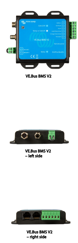
The BMS has the following LED indications:
• Status (blue): Lights shortly once every 10 seconds to indicate normal operation.
• Temp or Cell>4 V (red): Lights when the charge disconnect output is low because of cell overvoltage or overtemperature.
• Cell>2.8 V (blue): Lights when the load disconnect output is high and the battery cell voltages are above 2.8 V
No customer reviews for the moment.
You need to be logged in or create an account to give your appreciation of a review.